Configuration editor
The configuration editor is used for generating the configuration file, needed for and .
Notes
If the source module for a parameter uses the UDS protocol, contact us to help you with the configuration.
If the source module for a parameter uses the KWP protocol, the Block and Index match with the numbers found in diagnostic software.
Input fields for numbers with decimals only accept a point (.) and not a comma (,)!
Optional step
If you already have a configuration file that you would like to edit, press the Edit a previous configuration button at the top of the page and choose the file.

If you see the message The configuration must be updated to a newer version, you will be redirected to another page where the configuration file will be updated.
Press the Load the old configuration file button and select the file.

Select your target version from the drop-down list.
Press the Download the new configuration file button and the updated file will be downloaded.

You can now go back and edit the file.
Step 1: Change settings
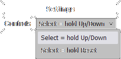
In the first section you will see a drop-down list of options for changing the way to select something in a menu.
Select = hold Up/DownTo select an option in a menu, hold the Up or Down button.
In this mode, it is possible to navigate quickly by holding Reset and Up/Down at the same time.
Select = hold ResetTo select an option in a menu, hold the Reset button.
In this mode, it is possible to navigate quickly by holding Up/Down.
Step 2: Choose included tools
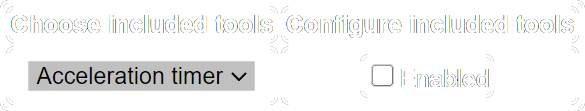
In the first section you will see a drop-down list of tools you can enable.
To enable a tool, select it and check the Enabled checkbox.
When a tool is enabled, you can configure it with the options that appear under Configure included tools.
Acceleration timer tool
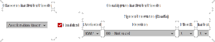
Choose from which module/location to get the current vehicle speed in km/h.
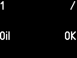
Oil level gauge tool
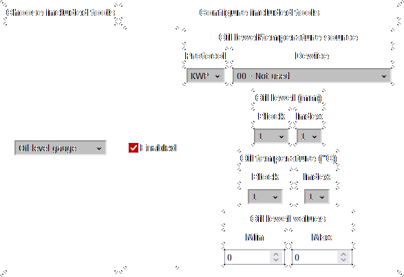
Choose from which module to get the current oil level and oil temperature.
Choose from which location to get the current oil level in mm.
Choose from which location to get the current oil temperature in °C.
Choose the correct oil level Min/Max values for your car, to display the level properly.
Engine mileage tool
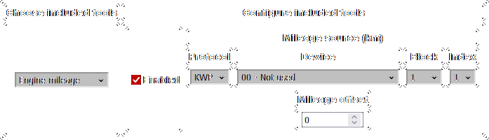
Choose from which module/location to get the current mileage in km.
Input a Mileage offset value, which will be subtracted from the odometer mileage to obtain the engine mileage.
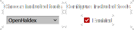
OpenHaldex tool
Step 3: Choose modules for ECU data
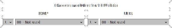
Here, you will choose from which modules you want to read parameters.
You have 5 slots for each protocol, and the order of the modules doesn't matter. It is also not a problem to leave empty slots.
If you want to get parameters from the Engine (KWP), AWD (KWP) and Transmission (UDS):
- In the
KWPcolumn select the number1and module 01 - Engine. - In the
KWPcolumn select the number2and module 22 - AWD. - In the
UDScolumn select the number1and module 02 - Auto Trans.
Step 4: Configure ECU data
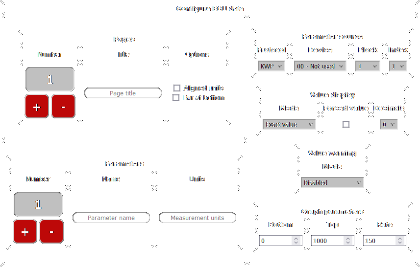
Here, you will configure each page for the menu.
When starting a new configuration (not editing a previous configuration), the first page and first parameter will be created.
Each page can have a title (optional, can be left empty) and between 1-5 parameters.
Each parameter can have a name (example: Oil) and measurement units (example: mm), but they are optional and can be left empty.
Pages
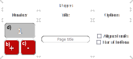
- To change the page's title, write something in the text box (or leave empty for no title).
- To add a new page, press the + button.
- When you have more pages, pressing the button will "insert" a new one right after the currently selected page.
- To add the page at the end, you have to first select the last page and then press +.
- To delete the currently selected page, press the - button.
- You cannot undo after deleting!
- To select another page (after adding more), press the box with the page number and select another one.
- To change some settings for the page, use the checkboxes.
Aligned units- enabling this will align all values and units to each other, instead of aligning them to the right edge of the screenBar at bottom- enabling this will move the additional bar (title/page counter/connection indicator) from the top to the bottom
Parameters
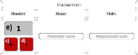
- To change the parameter's name, write something in the text box (or leave empty for no name).
- To change the parameter's measurement units, write something in the text box (or leave empty for no measurement units).
- To insert the degree symbol (°) for the measurement units, write the letters "deg", they will be replaced.
- If you don't want "deg" to be replaced, write "\deg".
- If you want "\deg", write "\\deg".
- Example: for °C, write "degC" in the measurement units text box.
- To add a new parameter to the page, press the + button.
- When you have more parameters, pressing the button will "insert" a new one right after the currently selected parameter.
- To add the parameter at the end, you have to first select the last parameter and then press +.
- To delete the currently selected parameter, press the - button.
- You cannot undo after deleting!
- To select another parameter (after adding more), press the box with the parameter number and select another one.
Parameter source
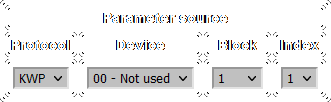
Here, you will select from which module/location the current parameter is read.
Value display
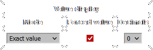
Mode: Exact value
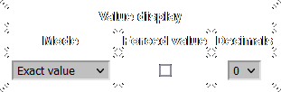
The parameter will be displayed exactly like in diagnostic software.
The Decimals drop-down selects how many digits are shown after the decimal point (0 for no decimal point).
For the KWP protocol, some parameters will be displayed as text instead of numbers. If you need these parameters to be shown as numbers instead of text, check the Forced value checkbox.
You can use this feature to find the value which corresponds to a certain text, if you need the Custom text mode (explained below).
The Forced value checkbox will have no effect for UDS modules.
Mode: Mapped value
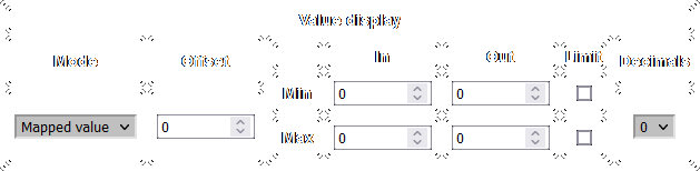
The parameter's value will be mapped to a range.
The Decimals drop-down selects how many digits are shown after the decimal point (0 for no decimal point).
To add a number to the value before mapping, enter this number in the Offset box (can be negative for subtraction).
The next section contains the map:
In Minwill be transformed toOut Min.In Maxwill be transformed toOut Max.- Every value between
In MinandIn Maxwill be scaled betweenOut MinandOut Max.
To prevent the value from going lower than Out Min, check the Limit checkbox on the same row as Min.
To prevent the value from going higher than Out Max, check the Limit checkbox on the same row as Max.
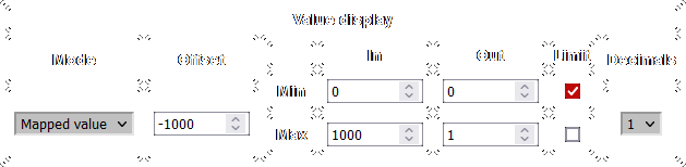
To display a "Boost" parameter, you should first subtract the atmospheric pressure (~1000 mbar) and then transform from mbar to bar.
- Write
-1000in theOffsetbox to subtract the atmospheric pressure (or write another number closer to your pressure). - Write
0forIn MinandOut Min,1000forIn Maxand1forOut Max. Now it is converted from mbar to bar (division by 1000). - Check the
Limitcheckbox on the same row asMin. Now the value can not become negative if the input is less than atmospheric pressure, but it can become more than 1 if the input is more than 1000. - Select the number of decimals according to preference.
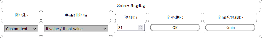
Mode: Custom text
Instead of showing a value, you can set your own custom text based on the parameter's value.
All number inputs for the conditions only accept whole numbers, without decimals.
Condition: If value / if not value
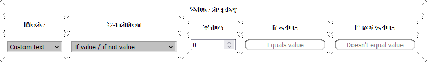
If the parameter is equal to Value, it displays the first text (If value).
If the parameter is not equal to Value, it displays the second text (If not value).
Condition: If inside / outside range
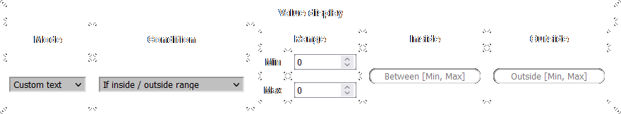
If the parameter is between Min/Max, it displays the first text (Inside).
If the parameter is lower than Min or higher than Max, it displays the second text (Outside).
Condition: If below / inside / above range
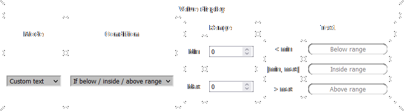
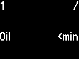
If the parameter is lower than Min, it displays the first text (< min).
If the parameter is between Min/Max, it displays the second text ([min, max]).
If the parameter is higher than Max, it displays the third text (> max).
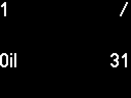
You get the oil pressure status from the Instrument Cluster (KWP), which appears as text (Oil Pr. 2 <min / Oil Pr. 2 OK), but you want to convert it to just <min / `OK``.
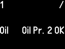
- In
Value display, select theExact valuemode and check theForced valuecheckbox to transform the text into a number, then save this configuration and upload it. - You see that
Oil Pr. 2 OKhas become the number31. - Edit the configuration, and now in
Value displayselect theCustom textmode, and theIf value / if not valuecondition. - Write the number
31forValueand the textOKin the first box and<minin the second box, then save this configuration and upload. - Now the custom text is displayed.
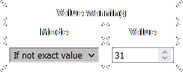
Value warning
Here, you can configure a warning mode, for example if a parameter's value is outside normal limits.
When a warning is triggered, the parameter's value (number/text) starts flashing until the error disappears.
All number inputs only accept whole numbers, without decimals.
Mode: Disabled
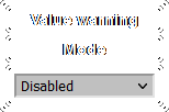
No warning for this parameter.
Mode: If exact value
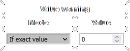
The warning will be triggered if the parameter's value is the same as what you selected.
Mode: If not exact value

The warning will be triggered if the parameter's value is not the same as what you selected.
Mode: If inside range
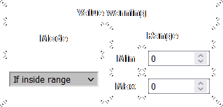
The warning will be triggered if the parameter's value is between the Min/Max you selected.
Mode: If not inside range
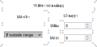
The warning will be triggered if the parameter's value is not between the Min/Max you selected.
In the previous example with the oil pressure, if you want to get a warning when it becomes <min, you can set the mode to If not exact value and write the number 31 for Value.
Graph parameters
Here, you can configure the default values that are applied when you select a parameter to graph.
You can also modify these in the menu, but setting them here will make it easier.
You can also input decimal values here, whereas you can only use integer numbers in the menu.
If you access a decimal value in the menu, it will be rounded to an integer number.
The decimal value will remain applied as long as you don't access it in the menu.
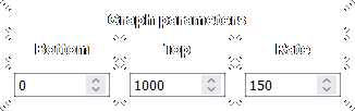
- - the lowest value the graph can show
- - the highest value the graph can show
- - how quickly to plot points (measured in milliseconds)
If Bottom has a higher value than Top, the graph will be inverted.
Parameters are read from the module as quickly as possible; Rate only changes how fast new points are plotted.
Setting Bottom to 0, Top to 1000 and Rate to 150 means the graph will show values between 0-1000 and a new point will be drawn every 150ms.
Step 5: Download
After everything is configured, press the Download the current configuration button at the bottom of the page.

The CANFIS_config.bin file will be downloaded, please save it to your device.
You are allowed to rename the configuration file. Please don't modify the extension, it must be .bin.